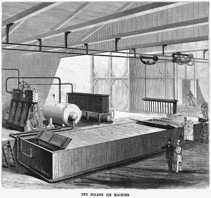
THE HOLDEN ICE MACHINE.
In our issue of August 18, 1877, we illustrated and described in detail the above named invention, showing its application to refrigerating purposes in breweries. The machine has recently been adapted to ice making, and has achieved, we are informed, very notable success. In using it for this purpose the manufacturers have added some valuable improvements which have materially increased its efficiency, and to these, more especially, it is our object now to direct the reader’s attention.
The machine is adapted to the use of any volatile liquid, such as common ether, methylic ether, chymogene, sulphurous oxide, etc., the vapor of which is used to lower the temperature of a non-congealable liquid, and this last freezes the water contained in suitable vessels and immersed in it. The action of the apparatus, as shown on the left of Fig. 1, is briefly as follows: A is the engine; B B are circulating pumps, which force the non-congealable liquid through a rotating coil in the cylinder, C, thence into the freezing tank, D. From the further extremities of the latter the liquid is conducted by the pipe, E, back to the pumps, and so passes again to the cylinder. At the bottom of the cylinder the ether or chymogene is placed so that the coil through which the water passes as it revolves dips in the volatile material, and the thin film of this which remains on the core is rapidly evaporated through the action of the pumps, F, which communicate with the cylinder by the pipe, G. In this way the temperature of the non-congealable liquid passing through the tubes is lowered. The vapor carried off by the pumps is by them driven into the condenser, H, and here it is cooled by water, liquefied and collected in the reservoir, I, whence it once more passes to the bottom of the cylinder, C. It will be noticed that there are two circulations, one of the non-congealable liquid, through cylinder, C, pumps, B, and tank, D, and another of the volatile material, or its vapor, through cylinder, C, pumps, F, condenser, H, and reservoir, 1.
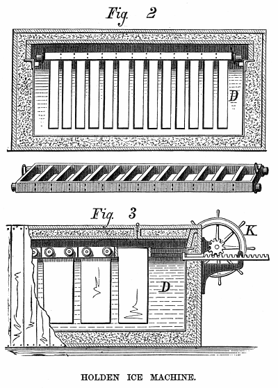
The new portions of the apparatus can now be clearly understood; and these are found in the tank, D, and its appurtenances. The water to be cooled is placed in deep cans, thirteen of which are set in a carrier, as shown in Fig. 2. When the cans are immersed in the tank, this carrier extends across the same, and the rollers at its extremities rest on ways made on the sides, as shown in the transverse section Fig. 3, page 162. The tank is capable of holding twenty-six of these carriers placed side by side. That is, this number would be inserted at the beginning of operations.
Above the tank is a traveling crane, which is used for lifting the carriers with their cans out of or into the freezing liquid Obviously the latter is coldest at its point of entry, and therefore the ice is removed by the crane from that extremity, and transported over the tank to a bath at J, into which the cans are dipped for a moment to loosen their contents, and the ice is then turned out on an inclined plane.
Meanwhile the attendant revolves the wheel, K, which, by a pinion, operates a rack which pushes the carriers bodily to the further end of the tank, so as to close up the space left by the carrier removed, and to afford a place on the right for the insertion of the same carrier, the cans of which are at once refilled with water. The crane then moves forward again and takes out the endmost carrier, and thus the operation continues, carriers newly filled being inserted at one extremity, while those the contents of the cans of which are frozen are removed from the other.
The economy of this arrangement will be obvious when the varying temperature of the liquid in the tank is remembered. The newly filled cans enter liquid of a temperature of, say, 320, a film of ice at once forms, and as they gradually move forward they are subjected to greater degrees of cold as the ice film thickens, until finally they reach the coldest point, when the warmth of the remaining uncongealed water has to be extracted through the greatest thickness of ice. The cold, to use a very unphilosophical but
[Continued on page 162.]
convenient term, is thus economized to the extent that, instead of the entire contents of the tank being reduced to, say, zero, the temperature of only a portion of the same is thus lowered, with equally as good results.
The manufacturers have recently constructed one of these machines for the Virginia and Gold Hill Water Company, of Virginia City, Nevada. From the report of the superintendent submitted, we learn that, although the contract requirement was 15 tons of ice in 24 hours on actual trial, the results exceeded 20 tons, with indications that even this yield could be surpassed, the apparatus working at only two thirds of its capacity. For brewers’ purposes the Holden machine is already favorably known through its successful use in the brewery of Messrs. Bergner & Engel, in Philadelphia.
For further particulars address the manufacturers, Messrs. D. L. Holden & Bros., Penn Iron Works, corner Beach and Palmer Sts., or P. 0. Box 1808, Philadelphia, Pa.
(page 159 & 162)
|

